Preparation and characterization of FBE powder coating
Related Product for Sale: FBE Powder Coating
Related Articles: FBE Powder Coating
2.4 Preparation and characterization of FBE powder coating
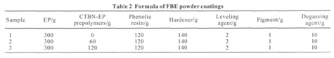
The epoxy resin, CTBN-EP prepolymers, curing agent and other raw materials were mixed in a highspeed extruder extruding (extruder I zone temperature set to 110 ± 2 ℃, II zone temperature set to 100 ± 2℃) according to the amounts shown in Table 2, Then through forming pressure tablets, crushing, milling, placing over 100 mesh sieve and other processes, the FBE powder coating was prepared after all of the processes were finished.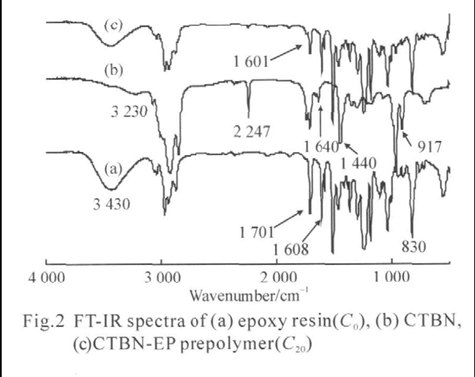
The size of the experimental substrate (tin plate) used in electrostatic spraying was about 150 mm × 70 mm × 1 mm. The substrates were treated through pickling, washing, blowing and drying out in the oven.The FBE powder coatings were sprayed uniformly on the substrates by electrostatic spraying; the coating thickness was controlled between 400 and 800 μm. The curing temperature of the epoxy powder coating was 230 ℃ and the time was 40 seconds.
The adhesion properties of FBE powder coatings were studied using a cupping testing machine. The resistance to bending test of FBE powder coatings was performed after the coatings were sprayed on the steel. The corrosion resistance of FBE powder coatings was studied by salt fog tester.
3 Results and discussion
3.1 Characterization of CTBN –EP prepolymers
FTIR spectra of pure epoxy (C0), CTBN and CTBN-EP prepolymers are shown in Figs.2(a-c). The pure epoxy resin (Fig.2(a)) shows peaks at 917 and 830 cm−1 are the existence of the oxirane group of the epoxy resin. The absorption bands at 1719 and 3230 cm−1 can be ascribed to the carboxylic group of CTBN (Fig.2(b)), but they were not observed in the FTIR spectum of blend sample C20 (Fig. 2(c)). The absence of the absorption band at 3430 cm−1 in a sample spectrum of samples (Fig.2(c)) could be ascribed to the OH groups of epoxy resin.
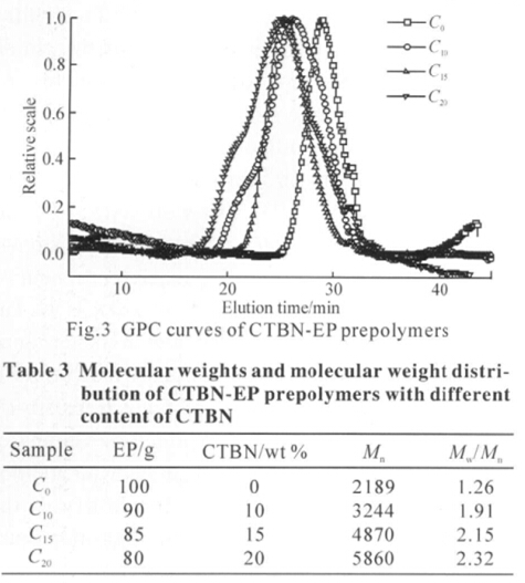 A sharp -C≡N peak at 2247 cm−1 is also observed in the spectrum of CTBN (Fig. 2(b)). The peak of -C≡ N group is weaker in Fig. 2(c), due to a decrease in the volume fraction of CTBN in the CTBN-EP prepolymer. The samples of CTBN-EP prepolymer also show a new peak at 1601 cm−1 due to C-C multiple bond stretching, which arises from the possible reaction shown in Fig.1. The molecular weights and molecular weight distribution of CTBN-EP prepolymers with different contents of CTBN were determined by GPC. As shown in the Fig.3 and Table 3, the molecular weight of CTBN-EP prepolymers increases upon the addition of CTBN. When the concentration of CTBN increases to 20%, the molecular weight increases to 5860. However, the molecular weight distribution of CTBNEP prepolymers widens with increasing CTBN content. It is shown that the addition of CTBN to epoxy resins caused a chemical reaction between the oxirane ring of the epoxy and the carboxyl groups of CTBN, which confi rms the results in the FTIR analysis.
3.2 Morphology analysis
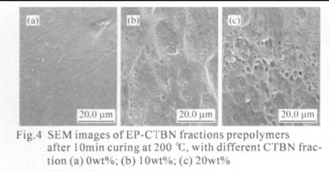
The fractured surfaces of the samples were examined using scanning electron microscopy (SEM). The surfaces of neat and of modified epoxies with different contents of CTBN are shown in Figs.4(a-c). The neat epoxy matrix, Fig.4(a), shows smooth, glassy, and river-like fractured surfaces with ripples. The
relative smoothness of the surface, irrespective of the presence of some shear deformation lines, indicates that no significant plastic deformation had occurred. The morphological development during cure can be correlated with the impact behavior. The ripples are due to the brittle fracturing of the network, which accounts for its poor impact strength, as there is no energy dissipation mechanism operating here. However, the fractured surface of the modifi ed epoxies (Figs.4(b-c)) clearly shows two distinct phases the continuous epoxy matrix and the dispersed rubber phase. Significant plastic deformation and many holes were found in the system. The plastic deformation and holes are due to the toughening fracture of the network, which accounts for its excellent impact strength, as there is an energy dissipation mechanism operating here. According to Yee and Pearson, the size of stress-whitened zone or the amount of deformation lines is proportional to the increase in toughness of the material. Relatively distorted rubber domain shape in these cured resin matrices is supposed to be attributed to an increased amount of plastic deformation. The deformation lines are propagated through rubber domains, promoting stress transfer between the particles and epoxy matrix. Also, less brightness of the interfacial layer around the rubber domains in the lower modified epoxies compared to the higher modifi ed samples is indicative of the interaction between the particles and epoxy matrix. The micrographs show stress-whitened zones of broken rubber particles. According to Lee et al and Bascom and Hunston, the stress-whitening is due to the scattering of visible light from the layers of the scattering center, which are voids developed in the matrix, due to cavitations of rubber particles. This has been explained by researchers as one of the most important energy dissipation mechanisms operating in rubber-modifi ed epoxies.
 D5 Creation
Comments are Closed